The pressure delay is caused by the elastic bending deformation of the roller under the action of the transverse pressure of the rubber material, and the center of the roller axis is offset from the original horizontal position by a certain distance, which is called the deflection of the roller. The deflection causes the thickness of the section in the width direction of the rolled semi-finished product to be uneven, the middle is thick, and the two sides are thin, which affects the calendering quality. In order to reduce this degree of influence, there are three types of compensation measures commonly used: the medium height method of the rolls, the roll axis crossing method, and the roll pre-bending method.
The medium height method is also called the concave and convex coefficient method. It is a concave or convex roller that has a working portion of the roll with a certain degree of concavity. The concavity and convexity coefficient is expressed by the difference between the center of the roller axis and the radius of the end section. The size and configuration method depends on the roller.
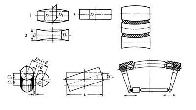
The shaft crossing method uses an auxiliary device to make the axis of the roller intersect a certain angle α, so that the gap between the two ends of the roller is larger than the gap at the center. The effect of the deflection on the nip is opposite, thereby compensating. The compensation effect increases as the angle of intersection increases. The value of α ranges from 0° to 2°, depending on the requirements of the compensation. The advantage of this method is that the compensation effect can be adjusted according to the nature of the rubber material and the process conditions. However, it is limited by the difference between the compensation curve and the deflection of the roller. In addition, the method is only suitable for single-roller transmission machines. The compensation principle is shown in the figure.
The roller pre-bending method uses an auxiliary hydraulic device at both ends of the roller to apply an external force to the roller to produce a pre-bending deformation opposite to the transverse pressure, thereby compensating, as shown in the figure. Because the method will increase the roller bearing load and limit its compensation.
It can be seen that the above several compensation methods cannot achieve complete compensation by using them alone. Therefore, two or three methods are usually used for compensation, but the requirements of the operational technology level are high, and the microcomputer operation is required.
There is also a more accurate compensation measure that is compensated by the floating roller method. This method is used for the wire radial tire inner lining laminating extension production line. It is made by forming the inner casing and the outer casing of the roller casing and the intermediate shaft. The solid shaft in the middle is fixed and does not rotate, only the hollow casing rotates. The sealing device is used to separate the cavity between the fixed shaft and the outer casing into upper and lower chambers. When working, the hydraulic pressure is only applied to the surface of the roller, so that the outer surface is in close contact with the surface of the deformed adjacent roller. Therefore, the pressure distribution in the longitudinal direction of the entire roller is uniform, and the rolling thickness of the rubber compound is also uniform.